Charging trolley, design-to-stock build
Team Bath Racing Electric
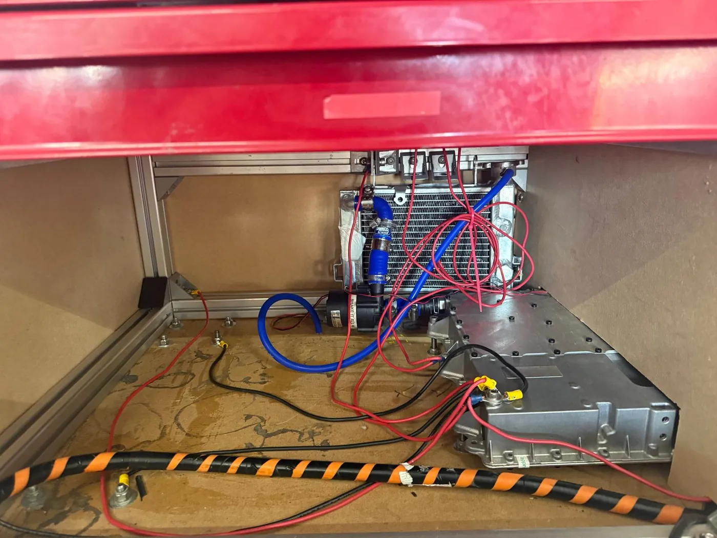
The new accumulator design meant a new trolley, designed from scratch to meet the rules, in the week before our first competition. I was given the overall frame and told to finish the mechanical design, which in practice meant everything between a frame and a working, legal trolley: the liquid cooling loop, the accumulator mounting points, the compartmentalisation the rules demand so that nothing high-voltage can be reached, the shield between the user and the accumulator, the panels and plates, and the drawers, cannibalised from an old tool chest. None of it was drawn in CAD. It was designed at the bench, from what the lab held, against a deadline that did not move. That is the judgement this build practised: where drawing effort adds value when you cannot order parts.
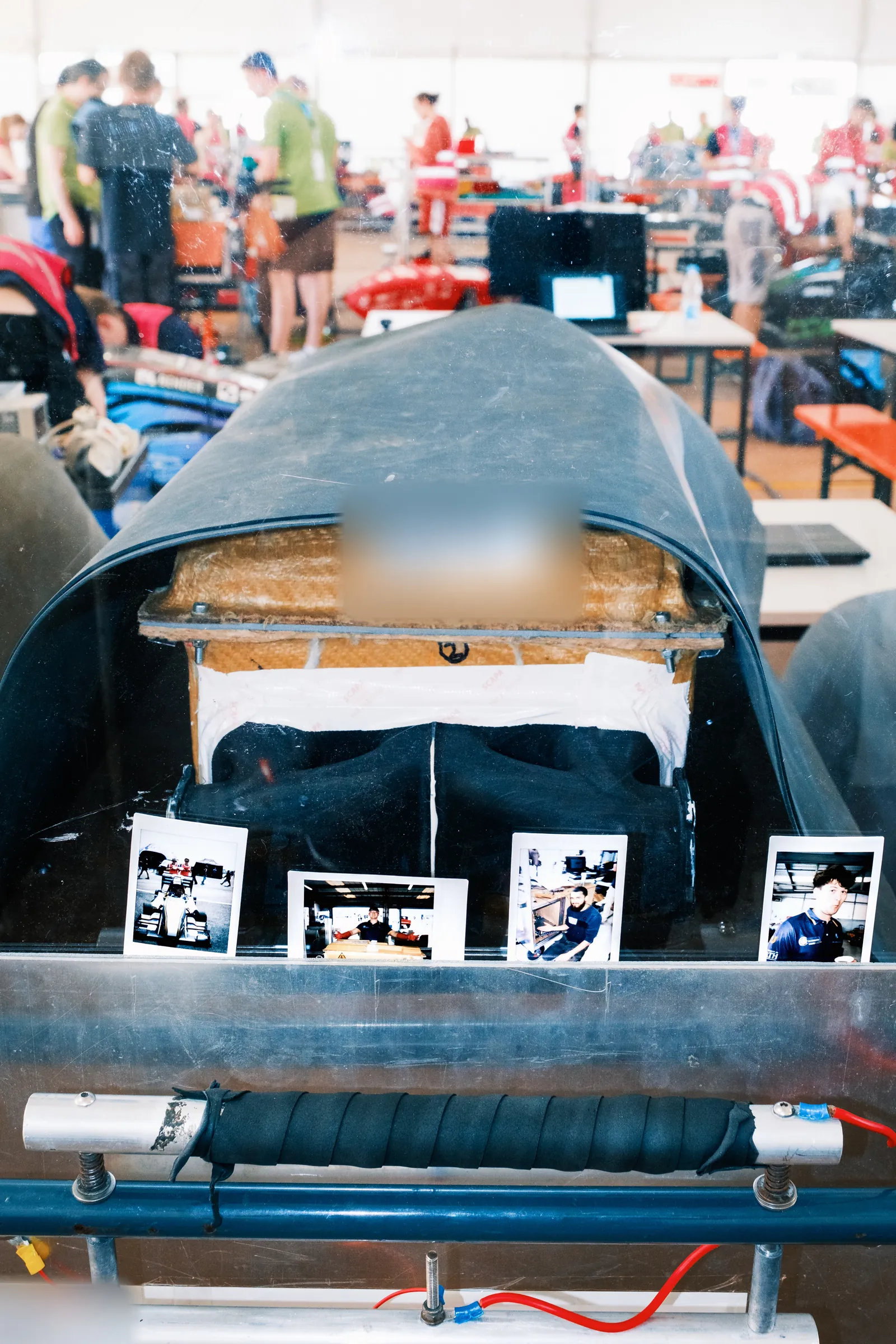
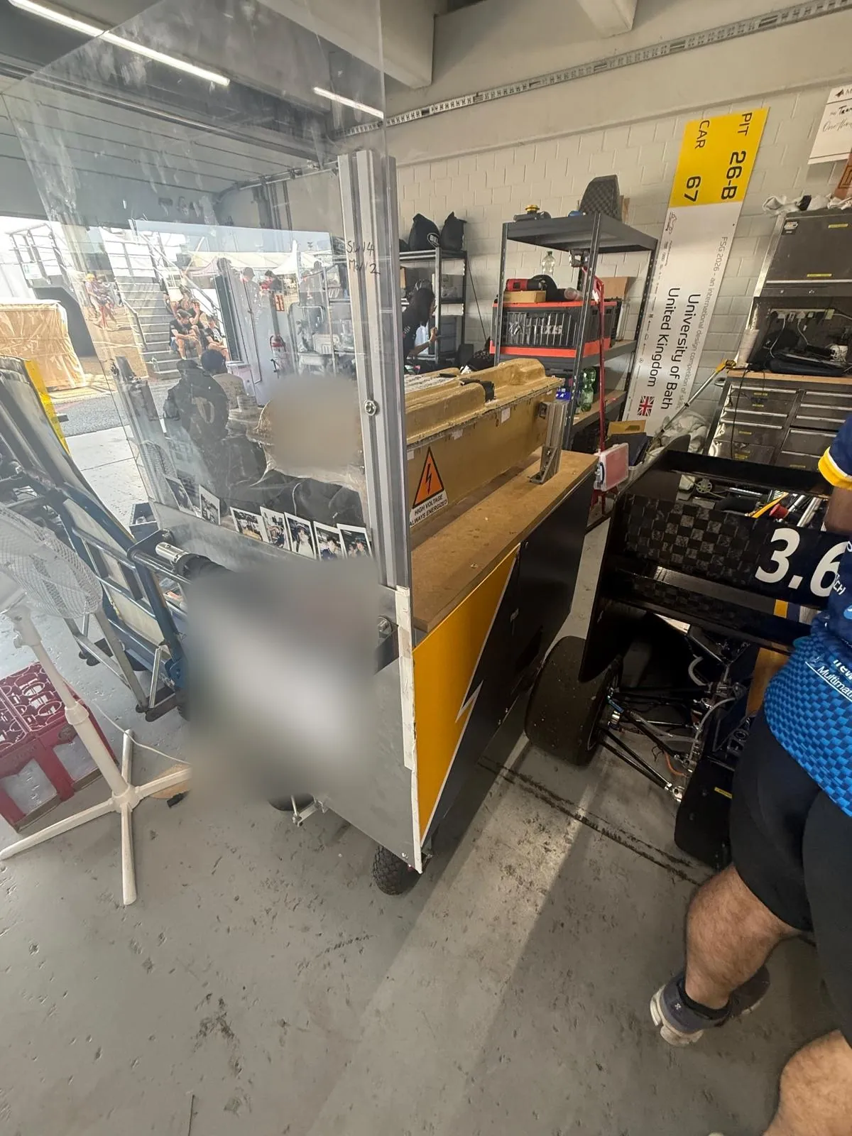
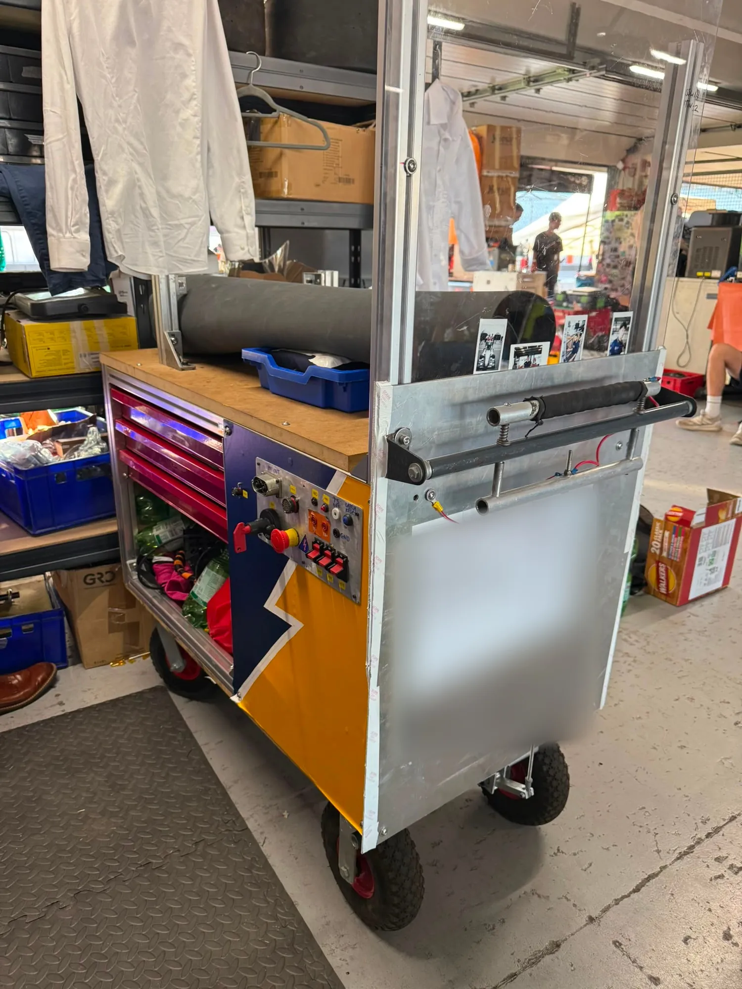
The competition rules require a printed sheet of emergency contact details taped to the trolley. It carries three people's names and phone numbers, so it is masked in every frame here that shows it.