Single-motor table tennis ball launcher
ME12001 Design and Make, University of Bath, Group 35
Team of six. My scope: aiming mechanism concept selected at evaluation, cam profile, gearbox design, co-built CAD assembly. Build pending university procurement.
The brief was a machine that lands four table tennis balls alternately in two zones of a table tennis table, on a 9 V battery, inside a 380 by 180 by 300 mm box, for under 85 pounds, with no glue, no welding and no CNC machining. Six of us took it from six independent concepts through a weighted evaluation to one CAD assembly. My scope was the aiming mechanism and the gearbox. Another member took firing and feeding, and the two of us built the assembly between us.
Aiming by inverted cam
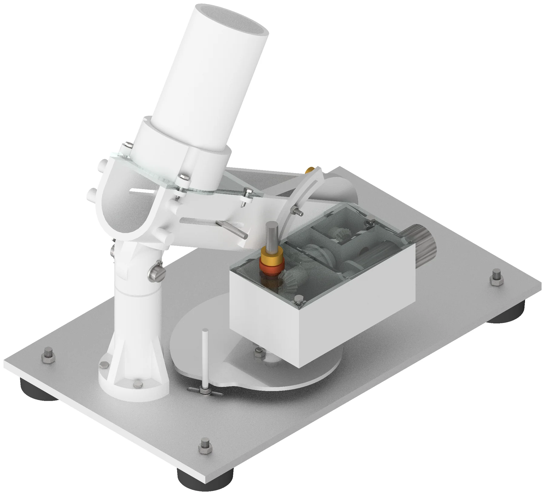
Aim is set by a cam rather than by timing. The shooting column swings on a pivot, and a cam disc carried on the swinging body bears against a pin fixed to the base plate. As the cam turns, its changing radius drives the body through its arc. A rubber band holds the pin against the profile, so the follower is force-closed and the cam needs no groove.
The complication is that the motor is mounted on the body it aims. The bevel pair holds a fixed relation between motor shaft and cam shaft in the body frame, so when the body swings through phi the cam is carried with it, and the motor turns the cam through theta on top of that. Absolute cam rotation is phi plus theta, and the profile has to be generated in that rotating frame. Generate it in the ground frame and every radius is referenced to the wrong angle.
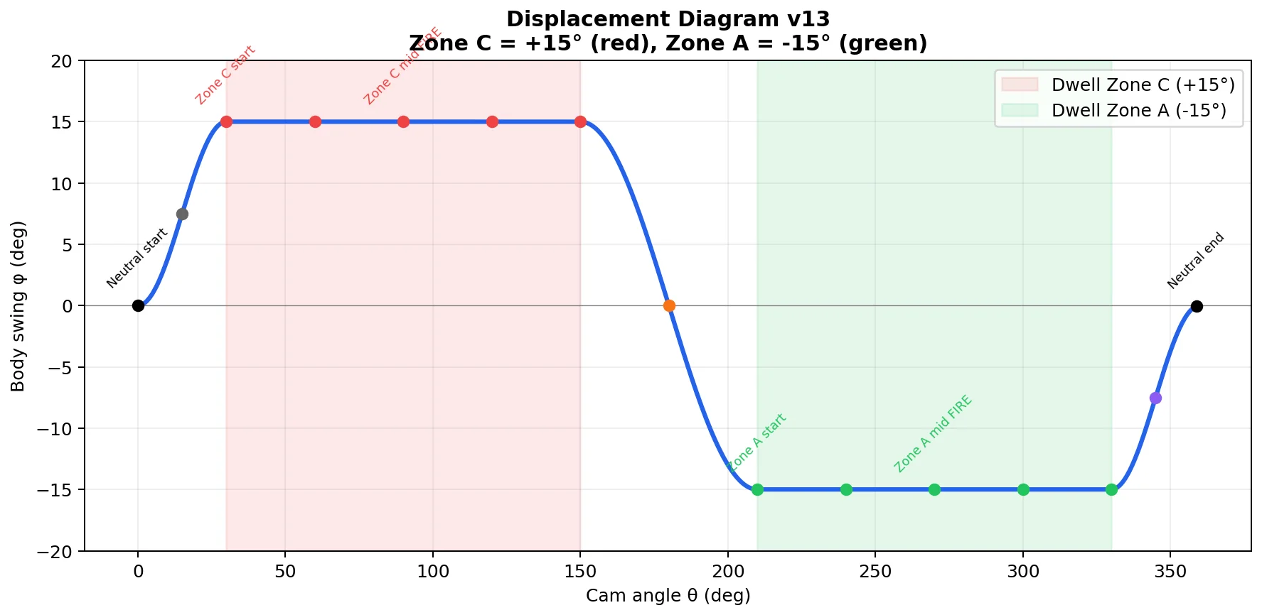
The profile holds the column stationary through each firing window: a rise, a 120 degree dwell at plus 15 degrees, a transition, a 120 degree dwell at minus 15 degrees, and a return. Two thirds of the cycle is dwell, so a ball fired anywhere inside a window still lands in the right zone, and aim never depends on firing timing. Phasing the cam 180 degrees on its shaft at assembly sets the required alternating sequence without touching the profile.
Sensitivity is a geometry problem
The first working profile was not buildable. With the pin close to the pivot the mechanism ran at 18.5 degrees of swing per millimetre of radial error. Six tolerances stack into that error: the laser-cut pin hole, cam shaft bearing slop, the cut profile itself, the bore to shaft fit, the bolt in its slot, and body flex under the rubber band. Combined on a root-sum-square basis they come to 0.38 mm, which becomes plus or minus 7.03 degrees of swing and an aim error of plus or minus 231 mm at the target. The zone half-width is 275 mm. The design had 44 mm of margin left.
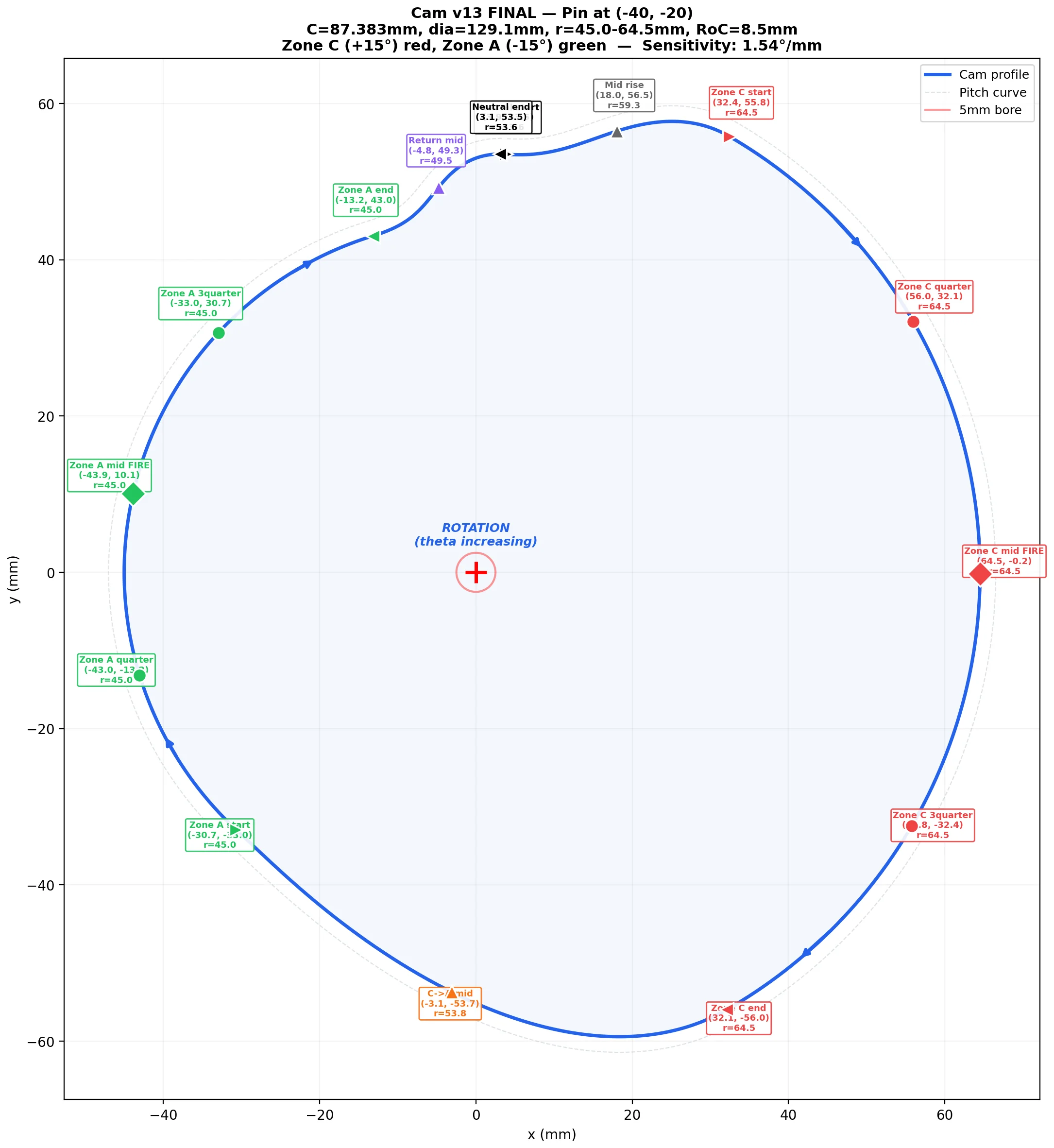
I moved the pin outboard, from 15 to 40 mm from the pivot along the x axis, which changes the error gain without changing the function. The same tolerance stack now produces 1.54 degrees per millimetre, plus or minus 0.58 degrees of swing, an aim error of plus or minus 20 mm, and 255 mm of margin against the same zone. I tightened nothing and specified nothing more precisely; I changed the geometry so the tolerances mattered less.
Two things follow. The radial range grows from 1.6 to 19.5 mm, which lowers the return force the rubber band has to provide. And the minimum radius of curvature stays at 4.3 times the pin radius, so the follower does not undercut anywhere on the profile. The pin sits in a 20 mm slot rather than a hole, which covers 20 to 35 degrees of launch angle, so the trajectory can be trimmed on the bench without a new cam.
A gearbox from a fixed catalogue
One motor drives firing, aiming and feeding, so the gearbox has to serve all three, and it has to run slowly. The output turns at roughly 8 to 9 rpm, which keeps the firing disc smooth and makes the cam dwells long in real time.
Two supply constraints shaped it more than any calculation did. The approved supplier sells 6 and 12 V motors and nothing at 9, so a 12 V motor is undervolted to the 9 V limit. No voltage against speed data exists for it, so a linear relation was assumed on technician guidance and the ratio chain sized against that. It is the weakest number in the design and the page says so. The bevel gear sizes the layout wanted were not stocked either, so ratios were iterated across what was available until the output speed fell out of the combination, rather than being chosen and then met.
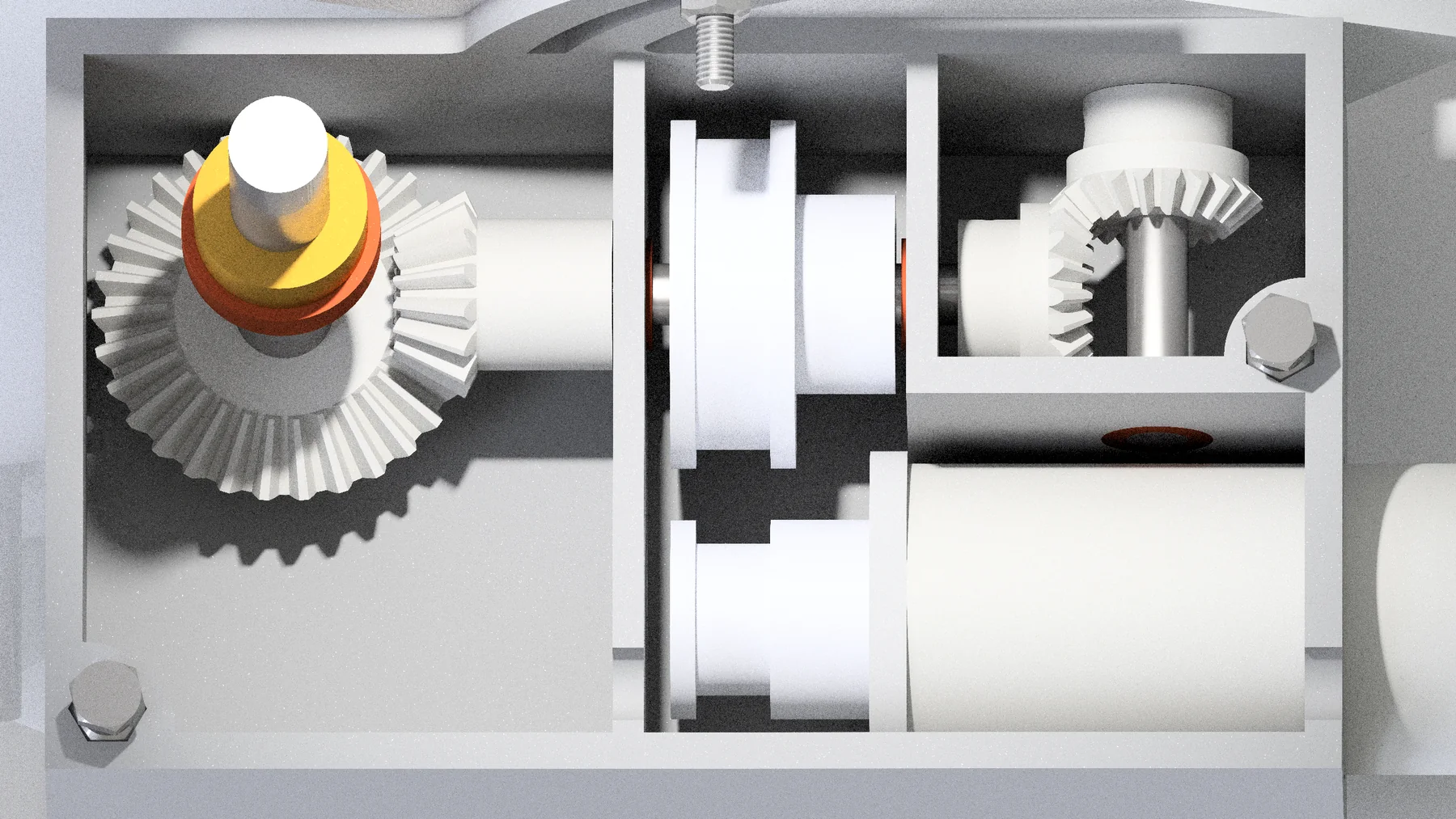
The case carries the reduction, the drive shaft and the battery, with the bevel pair taking drive up to the cam shaft on the swinging body. Gears are clamped by grub screws through tapped collars, because the threaded inserts the design wanted were the wrong sizes and expensive at this scale. That is the shape of the whole project: a mechanism designed around a catalogue, not around an ideal.